|
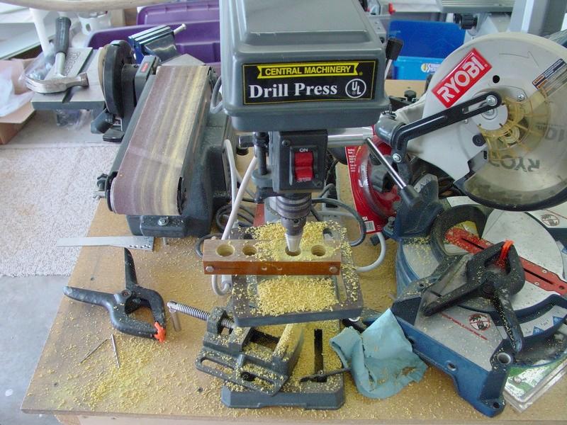
The rudder pedal mounts are constructed from 1"x1" phenolic bar. Two segments of bar are bolted together, and then drilled with a 1" diameter hole to accommodate the rudder pedal tubes. Through experimentation, I've found that it is best to progressively drill the holes, starting with a #40 and working up in small steps to the final size. Extra drill bits make convenient pins to hold the blocks in alignment.
|

|
The center 1" holes were practically made to be drilled with the #1 and #20 Unibit combination. Many builder suffer through drilling these holes with spade bits. I can tell you emphatically, that is NOT the way to do it! Using the unibit, there is no burning phenolic, no acrid smoke in the air, and no pestilent stink in the air afterwards!
|

|
It does make a mess, but it is a small price to pay, and your shop will thank you for it!
|

|
The completed blocks are ready for final chamfering and fitting to the rudder pedal tubes. Total time to construct: 1 hr.
|

|
I had heard from other builders the problem whereby the tail wheel pushrod caused the hole in the rudder drive plate to elongate, and become sloppy. The kit included a nice powder coated steel pushrod, but I decided to discard it and make my own. This way I could use a ball end bolted securely to the drive plate, thereby eliminating elongation of the hole.
|

|
The parts list and Wicks part number were as follows: 1 ft (cut to 7.5") of 0.305 ID 4130 chromoly steel tubing (R3/8x035-41), 2 threaded ball joint assemblies with 1/4-28 studs (CW-4S), 2 threaded rod ends, 3/8X035 1/4-28 (AN490HT6P), and 2 AN316-4 jam nuts.
|

|
The total cost was around $10, but it is adjustable and very smooth. Note, I mistakenly installed the tail wheel pushrod in the rudder cable hole (the outer hole on the rudder drive horn). Don't do like I did here!
|

|
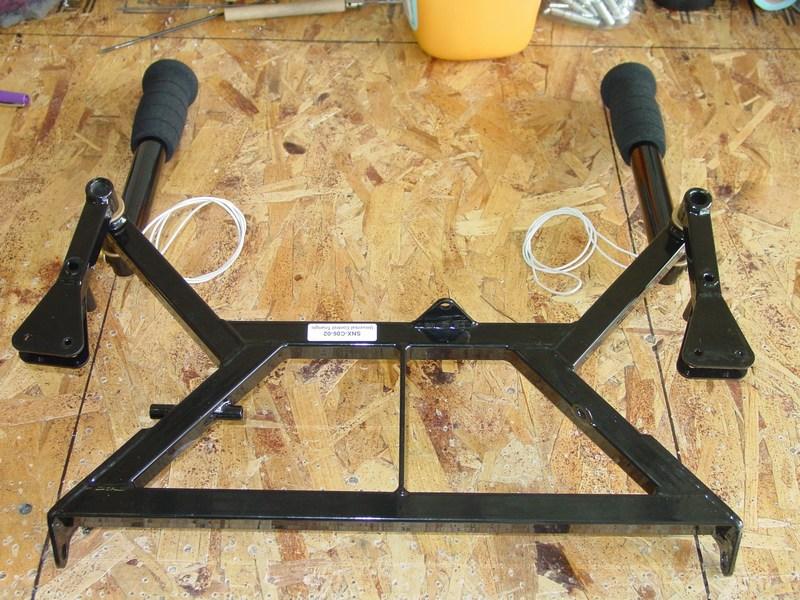
I am building a dual stick Sonex, and here is the control stick mechanism. Both stick grips are Ray Allen G101 with push to talk buttons. I really like the feel of these, and they look great. You do have to solder the wires onto the micro switch, but assembly is otherwise pretty easy.
|

|
Unfortunately, when I drilled one of the control sticks, it slipped out of alignment. As the photo shows, the top and bottom sections should have been lined up straight. In this one, the bottom was offset by about 1/3". This had the effect of making the connecting link bar too short.
|

|
My choices were too live with sticks that were never quite vertical, or to make a new link bar. I chose option three: make the old bar fit! I cut the bar in two and welded a 4130 steel sleeve over the two halves. This added the 1/2" or so that I needed.
|

|
The sleeve welded over the pushrod. The rivets were really only installed to hold the sleeve in alignment while it was being welded.
|

|
The finished and repainted link rod.
|

|
Aileron and Flap pushrods. These come nicely finished from the factory.
|

|
The rod ends are sized for 1/4" diameter bolts, and need to be sleeved down to 3/16" diameter with bronze bushings.
|

|
The bushing are a real tight fit, and need to be tapped in with a hammer. I used a bolt and a spare bushing to help fit the bushing in place.
|

|
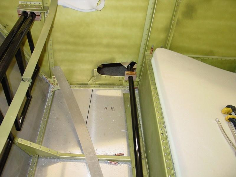
The rudder pedals are fit into place. They will not be installed until the interior has been painted, but fitting them now allows me to fine-tune the fit in the phenolic blocks.
|

|
The flap torque tube is also fitted now.
|

|
The weld on the lever end of the flap torque tube rubbed on the phenolic block. It needed quite a bit of chamfering with a rotary burr in my cordless drill in order to move freely. Now it moves very nicely!
|

|
The flap and brake levers are made from 3/16" x 1" aluminum bar. The grip area will be coated with vinyl tool-dip to give it a comfortable, non-slip grip.
|

|
Ready to paint.
|

|
All three handles were first painted with the epoxy white paint, then the tops dipped in "Grip Dip". This stuff was hard to find. Home Depot carries it, but not at all of their stores.
|

|
I dipped three coats, drying overnight between coats. This gave a nice thick, cushioned grip on the levers. Plus, the black looks really sharp contrasting against the white paint.
|

|
The flap stop bracket and trim lever installed on the sidewall.
|

|
The elevator trim cable attached.
|

|
Brake handle bracket installed. I originally had AN4-21 bolts here, but I switched them out for -22's.
|

|
Following painting the interior, the control stick assembly is installed. I discovered another minor mistake. The rivets were installed with the heads on the outside of the control stick brackets (supposed to be heads on the inside). This left the rivet body bumping up against the control stick. I had to remove a few rivets and put them in the right way.
|

|
The elevator pushrods are also connected to the control stick assembly and elevator idler.
|

|
It's only a minor discrepancy, but the plans show both elevator pushrods attached on the same side of the idler arm. However, they fit much better staggered like I have them here. The long pushrod (to the tail section) is nicely centered in the hole. The plans method had it way over to one side).
|

|
It's not really controls, but the seatbelts were installed as well. They fit with no issues or problems.
|

|
The brake cable link is made from aluminum bar stock. Once this part is finished, the brake handle can be installed.
|

|
Throttle cable installed in the corner bracket on the panel.
|

|
The cables penetrate the firewall on the right side, through grommets. The fit of the cable housing through the grommet is tight, so a bit of lithium grease helps.
|

|
The cable terminates into the built-in clamp on the AeroCarb. It seems to be a smooth setup.
|

|
The mixture cable will be positioned just to the left of the throttle. I fabricated a bracket that attaches the instrument panel cross tie.
|

|
Throttle and Mixture controls.
|

|
The rudder cable adjusters were fabricated and installed. For the first time I got to wiggle the tail from inside the cockpit!
|